
No question: the Commodore 128D is the finest Commodore 8-bit ever made. On this I tolerate no dissent, and that's not just because I sometimes hang out with Bil Herd. It's a 128, so it's got VDC graphics, 128K and 2MHz operation, but because it's a 128 it's also a 64. It's also an upgraded 128 with the fixed ROMs, (in this North American 128DCR) 8568 VDC and 64K of VDC memory, it's got a built-in 1571 (Commodore's finest 5.25" disk drive), and it doesn't have an external power brick. Plus, even though it has the desktop footprint of a 128, the detachable keyboard means you can just put a monitor on top of it (and the steel-cased North American 128DCR handles that very well) just like you can't with a flat 128, and you either get an actual cooling fan with the plastic 128D or the solder points to put one in a steel 128DCR. My only complaint is that the consolidated DCR motherboard is nearly devoid of socketed ICs, making it a little tough to do component level repair on. I like spares, so I have four DCRs, all of which completely or mostly work (and two spare keyboards, one rather yellow but fully functional and one even more yellow and useful just for parts).
This particular 128DCR has been a constant presence on my desk since the mid-1990s when I first got it as an upgrade from my ailing flat 128. But it has one flaw: it doesn't have a working CIA Time-of-Day clock, which isn't used much by software, so I never bothered to do anything about it. This was tricky when developing TOTP-C64, since the 30 second timer between emitting TOTP codes uses the TOD clock for maximum interval accuracy (the 50/60Hz Timer A interrupt that drives the TI/TI$ jiffy clock can be stalled and lose time, whereas the TOD clock is based on the AC mains frequency and thus is as accurate as your plugged-in wall clock); one of my portable SX-64 systems, my second favourite Commodore 8-bit, handled that portion of testing instead.
Well, now that I've got a new Ultimate II+L cartridge in fire-engine red with its own real-time clock (among other great features), I'd like to update TOTP-C64 to support it and I'd rather do it on the 128DCR. That means we should fix the TOD clock. And that means ... a Refurb Weekend!
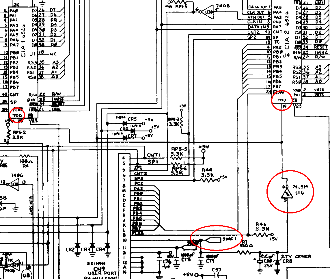
Another great thing about Commodore 8-bits: schematics. Both the Commodore 64 and Commodore 128 Programmer's Reference Guides have schematics, though this one is out of Commodore's 128/128D service manual.
Here we can see the path the signals take to the TOD pins of both of the 128's CIA I/O chips. Since neither TOD clock is working and both CIAs otherwise work fine — joysticks, keyboard, user port and IEC serial all operate normally — we can confidently surmise the problem is the input they're receiving. The AC frequency is transmitted on a 9V AC line from the power supply, goes through a couple capacitors connected to ground, a resistor and a 2.7V Zener diode also to ground, and then through the 74LS14 at U16, a Schmitt trigger-inverter that turns the AC waveform into pulses which are fed to both CIAs. A failure could theoretically occur at any level.
The schematic also shows us that the 9V AC is exposed on pins 10 and 11 of the user port. We'll plug in our user port breakout card (though you can also just test the card edge contacts) and see what we get.
The red LED tells us we have +5V DC on the user port (or the computer wouldn't have worked at all), but we're getting fat nothing on the user port AC pins. Because the schematic shows us those lines come directly off the power supply, it looks like our TOD clock problem might actually be a power supply problem. Let's check it out.
Ready for disassembly!
It's a shame to break a pristine warranty label, though the glue has weakened enough we were able to get this sticker loosened up intact. Don't tell the local Commodore authorized quality service center.
Besides the three screws on the rear holding the top case on, there are also screws on the underside.
With those removed and the warranty seal gently freed, the top case pulls back and off.
And here's the interior. The 1571's drive mechanism is at the top left, but the 1571's electronics and the 128 proper share a single unified logic board except for their joint power supply, which is the daughterboard at lower right with the big transformer.
Rarely do you get to see
three CPUs on the same logic board from this era, but here they are: the 128's MOS 8502 (an upgraded, 2MHz-capable version of the HMOS-II 8500, itself a repackage of the original NMOS 6510, a 6502 with an on-board I/O port used for memory banking and the cassette port) and 4MHz Zilog Z80 CPUs next to the 1571's own 1MHz MOS 6502. The other major chips visible are the (one of two) 318022-02 Commodore BASIC 7.0 ROM, the MOS 8580 SID sound chip, and the MOS 8721 PLA and MOS 8722 MMU, used for the 128's rather complicated internal banked memory scheme.
The power supply connector plugs into the middle of the board, labeled CN7 on the schematics. In this view pin 1 is north and pin 6 is south, with pins 5 and 6 carrying the 9V AC lines (pin 4 has 5V DC, 3 and 1 are ground, and 2 is 12V DC). To see if the board or the PSU is the problem, we'll test the 9V coming directly from the connector on those two pins, and we also get zero volts. It looks like the power supply is indeed at fault.
For this next section, grateful acknowledgment is made to Ray Carlsen, the patron saint of Commodore power supplies, who provided me helpful advice and offers Commodore power supply sales and repair.
The schematic of the 128DCR PSU from the Commodore service manual is grossly inaccurate because (among other things) it completely omits the 12 volt line; refer instead to the collection of DCR power supply schematics
provided by Bo Zimmerman. However, I use it here because it's simple and it's absolutely right about one thing: the 9V AC lines come nearly directly off the main transformer. There's just not a lot to go wrong, and Ray describes the DCR's switching supply as generally reliable unlike the infamous C64 epoxy bricks.
The most common failure that would explain these specific symptoms would be the fuse at F2 (if the fuse at F1 were blown, the system wouldn't power on either), though the service manual is incorrect about their values as these are both 250V fuses, with F2 being 1A and F1 being 2A. Here are the two blown DCR PSU fuses from this entry for your amusement, one a subtle fault where the thin wire snapped, and a massive blowout that I actually caused myself (yikes). Naturally both of these faults, plus other not immediately noticed defects, are easily discovered with a continuity tester and/or ohmmeter.
On the Mitsumi power supply in this unit, the fuses are labeled F101 and F201, with the fuse of interest (F201) at the lower right. Both check out with no detectable resistance and full continuity.
Since any further diagnosis will require getting it on the workbench, our next step will be to swap this power supply out for one of the spares. Interestingly, the first one I grabbed also has no 9V AC, so I put that unit aside for analysis as well (we'll come back to it). The second one checked out fully. We'll install that one to get back up and running and then test at leisure.
Screws on the side and rear hold the power supply assembly in place, along with an sunken-down screw near the power connectors that holds it into a standoff. With those removed and the connector disconnected, the entire assembly lifts out as one piece.
The replacement supply has been extracted and is ready for exchange.
Installing the replacement supply, lifting it up slightly so that the screws meet.
However, there's one wrinkle here: this is a different variant of the Mitsumi that has a different power LED connector. Both of the spare units at my disposal had this differing black connector; the fourth unit was at the storage unit and not immediately accessible. Naturally you could cut and swap the connectors, but I decided simply to switch power LEDs at the same time.
In retrospect it was probably more trouble than it's worth to do so, but if you decide to switch the power LEDs you should keep in mind that both front LEDs (i.e., the red power LED and the green disk access LED) are on little tiny circuit boards wedged into clips in the front plastic case. Remove the screw and then try to worm it out. Odds are you'll crack the clip, but as long as the screw is put back it will stay in place.
Now measuring 10 volts on the AC lines (within specification), the DCR is ready to go back in service.
With the unit back in action, let's now have a look at our two 9V-less power supplies, starting with the original one. Since its fuses checked out, Ray suggested checking the transformer windings next.
With the screws holding the board onto the frame removed and the board turned over, we see the primary and secondary sides of the DCR's switching power supply separated by the orange silkscreened line. South in this view are (on the secondary side) the two secondary windings next to the nylon hex nut and (on the primary side) the single secondary winding. The secondary windings had continuity with zero resistance. The primary winding didn't. While checking voltages this is where I ended up explosively blowing that blackened fuse you saw, so at this point rather than risk a one-way electrified trip to the vintage computer museum in the sky it was time to send it to Ray for professional evaluation and to repair or replace the main transformer.

The second 9V-less supply was more straight-forward, merely a bad F2/F201 fuse (the second, more subtly failed fuse I showed you). I replaced that and the supply was again fully operational. It's not clear what caused it to blow but it seemed to burn in fine, so I marked the PSU good and returned it to the spare pile.
Meanwhile, the PSU with the bad transformer I shipped off to Ray came back fully functional. What Ray had done was clip the skirt and tape off the main transformer and discovered a small mini-fuse (a wire, really) had opened. (Did you know the transformer has its
own fuse? I didn't.) It's not clear what did that and it could have simply been a transient overload. Ray glued a replacement mini-fuse in and verified operation — because why would we throw out a transformer that could be repaired? The repair cost was perfectly reasonable and I bought some additional Commodore cables from him at the same time that I've been short on.
While this fix technically exposes the high voltage within the primary winding, and thus is a repair only a professional should attempt, there are plenty of places you could short the PSU when energized separate from that (as I can personally attest). This one's in the spare pile too, ready for use, though I'll need to switch the LEDs back if I need to install it.
And now the TOD clock works, as
demonstrated in TOTP-C64. With another successful Refurb Weekend in the can, it's time to do some more hacking on my favourite Commodore 8-bit. Stay tuned.


No comments:
Post a Comment
Comments are subject to moderation. Be nice.