
This is the bigger, more deluxe of the two Mattel dedicated D&D games (the Intellivision of course had its own set, and we had a Tandyvision ourselves), the other being the DUNGEONS & DRAGONS™ Computer Fantasy Game. That was a handheld unit with a surprisingly compelling implementation of Hunt the Wumpus, and something we might talk about another time. This one is more like a board game, but with a computer antagonist and audio.

Well, better late than never. And hey: let's find out what makes it tick. (Teaser: it's four bits and we have an annotated die photo. Read on.)


At its heart overall gameplay is, as the name suggests, a turn-based maze crawl in an eight-by-eight dungeon. The raised indentations between board spaces are for placing red "walls" as you run into them to build up the maze visually. The game tells you what's happening with twelve unique audio cues; since you have to know what they mean, the bottommost six keys on the left play them for you on demand (with the SWITCH key, they play the second bank of six). However, they're all fairly distinctive and suggest their meanings well, so I don't recall we had any trouble remembering them. The basic idea is to get the treasure and get back to your hideout before the other player gets it or the dragon gets you. A higher difficulty setting adds "doors" that randomly open and close, but this is annoying, and I'm pretty sure we played that mode exactly once. You could probably play a decent game in about ten or fifteen minutes.
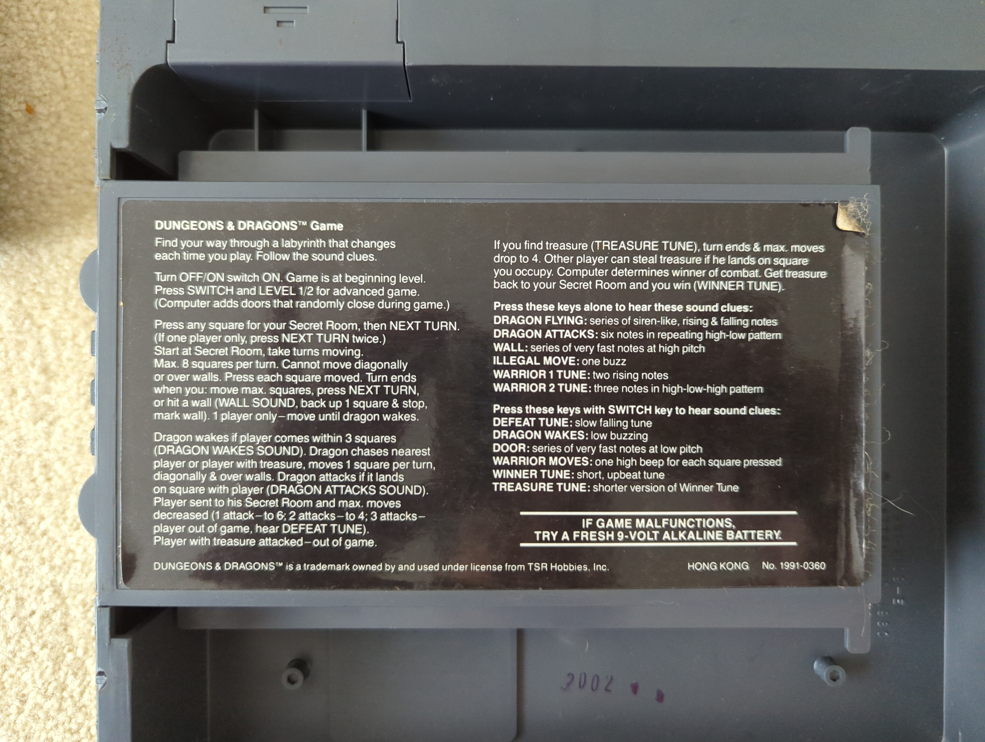
The game runs on a single 9V battery, but you can also use an AC adapter (not included). As the sticker says, if the game is acting weird, replace the battery. I should try that with my cat but I don't know where her battery compartment is, exactly.


The three green tokens are for marking the player's secret rooms (start and finish) and where the treasure room was so that the treasure can be returned there if an unfortunate player loses it. The treasure piece is mostly for show because the player that has it will take it, leaving the green token in its place. But it looks cool.


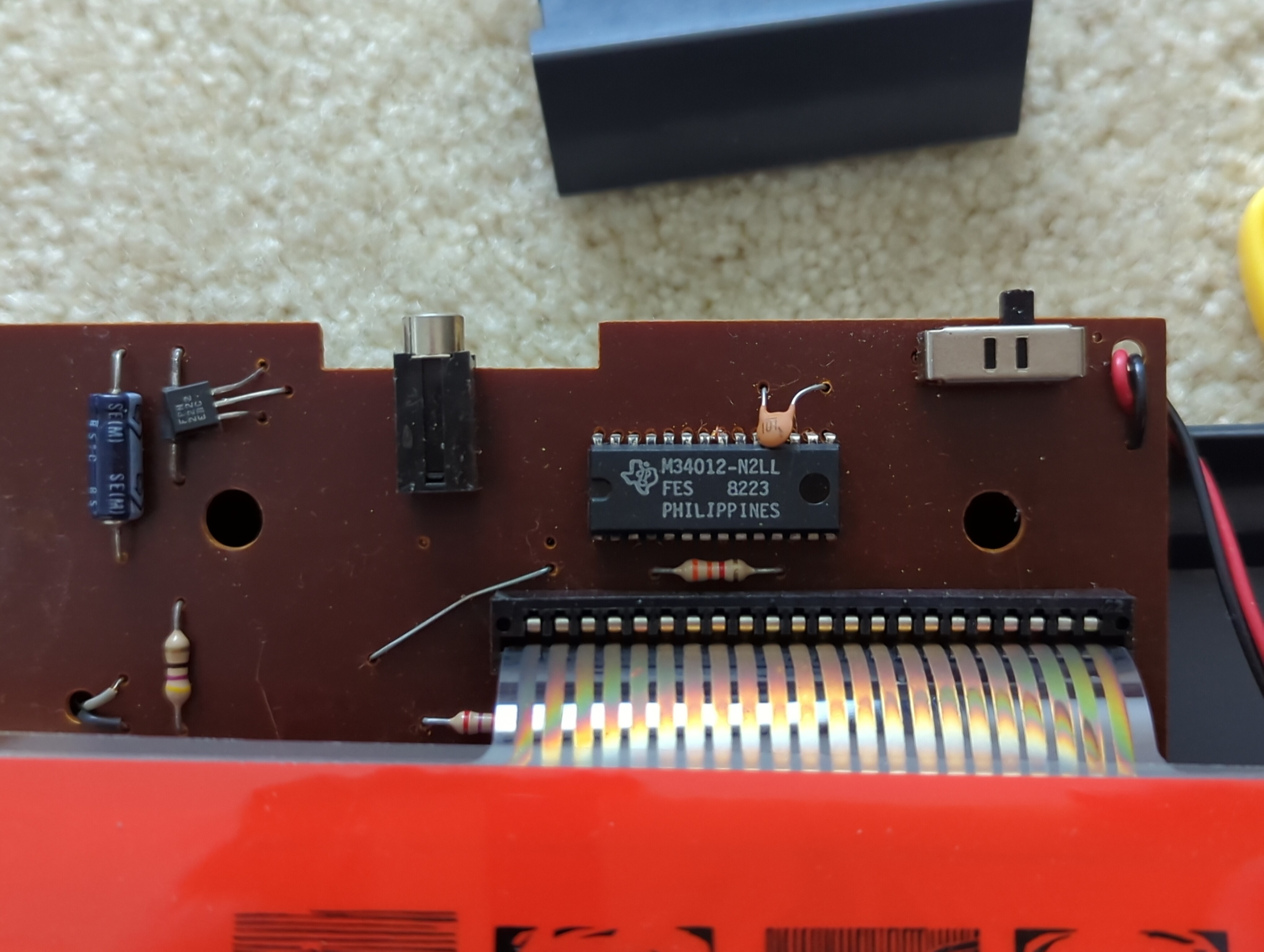

Let's talk about the CPU. Though the chip number might allege this to be related to the Texas Instruments TMS34010, this chip is both way too early and way too small. We need something simple, inexpensive and easy to mass produce for a kid's toy, and Texas Instruments had just the ticket.
The M34012 is in fact an iteration of the Texas Instruments TMS1100 microcontroller, itself an evolution of the original TMS1000 and that a descendant of the TMS0100, which in 1971 was the world's first microcontroller. These chips contain RAM, ROM and I/O all on one die, including support for segment displays and reading keypresses, all with a very low requirement for external supporting components. The TMS0100 was first used (as the TMS1802NC) in the trend-setting Sinclair Executive handheld calculator and was very successful in that application. TI reworked the TMS0100 design into the TMS1000 line in 1974, and modestly upgraded the RAM and ROM to yield the TMS1100 series in 1975. The M34012 is a PMOS part, allowing it to run pretty much directly off a 9 volt battery or other unregulated supply of similar voltage.
Unlike our other favourite game microcontroller, the MOS Technology 7600, where no one has found a data sheet or even a product circular yet [update: someone has!], the TMS1000/1100 family was copiously documented — sufficiently so to even facilitate writing MAME drivers for such games. The output programmable logic array (PLA) and even the instruction decoder PLA were customizeable: provide the PLAs and the mask ROM to Texas Instruments with a wad of cash, and get back an almost-all-in-one drop-in game controller in large quantities. TI not only used it in their own consumer toys like the Speak & Spell but also the Milton Bradley (now Hasbro) Simon game, the Parker Brothers Merlin, and the Milton Bradley Microvision, the first handheld game with interchangeable cartridges (after the Intel 8021's power consumption proved too high). By 1979, TI reportedly sold around 26 million parts in the family annually and its NMOS and CMOS descendants were used well into the late 1980s.

MAME estimates its clock speed at 475kHz based on the values of the resistor and capacitor nearest the chip, though this value tended to wander. All instructions execute in a single clock cycle. The chip provides four inputs (K-inputs, for the keyboard lines), and nineteen outputs in two groups, one group of eight simultaneously set by the output PLA from a five-bit output register (O-outputs) and eleven more that are individually controllable (R-outputs). TI envisioned the R-outputs serving as control lines and the O-outputs for LED segments, but in this game all the O-outputs and all but one of the R-outputs service the keypad; the remaining R-output goes to the speaker. Since there are four inputs, there are two halves to the keypad consisting of four rows each. The game energizes each of the nine columns in each half using a different output line (thus 18). Any buttons pressed are transmitted back on the K-inputs.
The TMS1000 family is Harvard architecture, so the ROM occupies a different address range from the RAM. The TMS1000 has 43 instructions, 12 operated by fixed logic and the rest sequenced by the PLA (in the TMS1100, this was increased to 54 and some were slightly altered). Like most companies, Mattel used one of TI's standard instruction decoder PLAs and did not use a custom one. However, virtually every TMS1000-family part including this one has a customized output PLA because of the sometimes complicated mapping of five bits onto eight. MAME requires the ROM and the contents of both PLAs to play a game.

Even though each instruction is only a single byte, a six bit program counter means you can only address 64 bytes of ROM, so PA picks one of 16 pages. On startup PA is set to page 15 and PC is 0. The program counter wraps, meaning after byte 63 comes byte 0 again in the same page, and on top of that, the only branch instructions you have only branch if S is true. To make a far jump or call, you need to make sure S is true (executing a dummy instruction or a known-true to make it so if needed), set PB to the desired page (LDP x), and then branch (BR): the CPU puts PB into PA and starts from the new PC in the new page. Calls (CALL) swap PB and PA to preserve the return address, meaning you can't make a long call from within a subroutine, and until CL is cleared by a RETN instruction, subsequent calls do not change SR or PB which still point to the original return address and page. Once a branch executes, taken or not, S becomes true again.
The program flow situation becomes a bit more complex still in the TMS1100: now you have double the ROM, so a set of one-bit chapter latches were added for the new second bank. Analogous to SR, PA and PB, you have CS (chapter subroutine), CA (chapter address) and CB (chapter buffer), all zero on power-on. The new COMC instruction flips CB. On a branch, CA is set to CB at the same time PA is set to PB; on a call, CS is set to CA as well so returns still work.
Likewise, as Y is used as an index into RAM, only 16 of the 64 nybbles in the TMS1000 can be addressed with Y alone; the two-bit X serves as the RAM page register and selects the "file." The TMS1100 also has double the RAM, but here the solution was simply to make X three bits instead and change the corresponding LDX instruction accordingly. However, a possible design flaw only allows Y to index the R-outputs when the third bit isn't set, so COMX was altered to flip only that new bit instead of complementing the entire register. (Y values 11 to 15 only set R-outputs on the expanded TMS1200 and TMS1300 chips, which have 16 such outputs instead of 11.)
The 4-bit adder in the die picture does double duty as a comparator, and adder output can go either to A or Y — or neither (the small band of circuitry under the adder chooses the destination). Carry or borrow, if there is one, goes to S. All the ALU does is add and subtract; there are no bitwise logic instructions. On the other hand, the SBIT and RBIT instructions can put a 0 or 1 at any bit position in any nybble indexed by X and Y, and TBIT1 can test it (bit to S), so any logic operation could be (labouriously) implemented by walking all four bits and setting appropriately.
The accumulator is the only register that can write the O-output register, but because it's only four bits, the fifth bit has to come from S. There are some memory-to-memory instructions and even a constant-to-memory instruction (TCMIY), but of the registers only the accumulator can load and store from memory, only the accumulator can add and subtract with values in memory, only the accumulator can receive the contents of the K-inputs (though you can also test them as a group), only the accumulator can be compared against (to memory or Y, result to S) and only the accumulator can add or subtract a value greater than one.
With all that in mind, consider these programs, directly copied out of the programmer's manual. This first one does a left shift of six nybbles in memory, position 0 being the least significant digit, such as you entering a new digit into a calculator value.
lshft   cla     ; clear A
ldata   tcy 0   ; transfer constant 0 to y
l1      xma     ; exchange memory indexed by Y and the accumulator
        iyc     ; y++, carry to S
        ynec 7  ; s = (y!=7)
        br l1   ; branch if true to l1

        retn    ; if this were a call
If entered at ldata, then the accumulator is put into the LSD instead of zero.
And here's an addition routine between two banks of six nybbles. Because this is intended for a calculator, it does it in binary-coded decimal treating each nybble as a digit. X sets the destination of the sum, flipping the upper bit; thus, on a TMS1100 with an X of 0, this means you would add the digits in file 0 to file 4 and store them in file 0, and so forth. The 1100 lacks the ALEC (A less than constant) instruction that the TMS1000 had which prevents a direct test to see if our digit is already in range, requiring some extra footwork.
a040    tcy 0
        cla
ad1     comx    ; flip X bit 3 (note: on TMS1000 this flips both bits of X)
        amaac   ; add m(x,y) to accumulator, carry to S, result to accumulator
        comx
        amaac
        br gt15 ; branch if carry set (greater than 15)
        a6aac   ; add six to digit. 10 becomes 16, which is zero, etc. (carry to S)
        br gt9  ; greater than 10
        a10aac  ; add ten to digit to fix a digit less than 9
        tamza   ; transfer accumulator to memory indexed by Y and clear accumulator
        br incy
gt15    a6aac   ; 16 becomes 6, 17 becomes 7, etc.
gt9     tamza
        iac     ; increment accumulator, inverse of carry to S
incy    iyc
        ynec 7
        br ad1
        retn
(The AnAAC series of instructions are actually one group of microcoded instructions with multiple mnemonics but a non-standard constant encoding; CLA and IAC are also related.)
And finally here's a routine that emits six nybbles as segments on the O-outputs, pulling each R-output low from 6 left to 0 right so that the display knows which digit is being emitted, in a loop until any key is sensed on the K-inputs, then debounces that key. This assumes a seven-segment digit-to-LED mapping is in the output PLA.
disp    tcy 7
dis1    dyn     ; y--, inverse of borrow to S
        tma
        iyc
        rstr    ; R(Y)=0
        dyn
        tdo     ; O=A
        setr    ; R(Y)=1
        knez    ; any K bits set?
        br exit ; yup
        ynec 15 ; s = (y!=15) which would mean it underflowed
        br dis1 ; continue digits
        br disp ; start over from the left
exit    tcy 15
        tya     ; transfer Y to A; can't load non-zero constants to A directly
delay   dan     ; decrement A, inverse of borrow to S
        br delay; branch as long as we don't borrow
        dyn
        br delay
        ; total delay 544 cycles
If you actually wanted the value of K, you could fetch it before the delay with TKA and stash the accumulator somewhere in memory beforehand.
Extra RAM could also be controlled by the R-outputs. For a 256x4 bit RAM chip, for example, the microcontroller might put the address on R(0) through R(7), Chip Select on R(8) and Read/Write on R(9), emit data to write on the O-output's low nybble and read data on the K-inputs. A multiplexing system could allow the lines to be used for other purposes, though we're getting to the point where a more capable processor might be more appropriate. Fortunately for Mattel the small amount of RAM built-in was clearly more than enough to manage this game's state, players' conditions and one very cheesed off dragon.


What was the gameplay like? I remember these, but never had one. We had the non-electronic Dungeon (still have my set!) and had a great time playing it! It makes think of The Wizard's Castle and the other "Grid CRPGs" that followed it. I played quite a bit of the Leygref's castle variant prior to obtaining a copy of Ultima III for my Tandy which took me in a new direction.
ReplyDeleteWell, basically, like stumbling around in a dungeon with the lights off. No real RPG elements to speak of. I was probably too young for it at the time, but it's unique and fun for a light diversion now.
DeleteI think this thing has the same CPU as my old Microcomputer Trainer - https://vimeo.com/63990422.
ReplyDeleteSort of (I saw your comment on Lobsters and replied there too). It does seem that the Science Fair Microcomputer Trainer does use a TMS1000-family CPU, probably an 1100 based on the reported number of nybbles, but because it's Harvard architecture there's no way it could execute from RAM. Instead, it looks like it implements a basic virtual machine and you write the assembly code in that. Interesting, though!
Delete(see also https://www.instructables.com/Radio-Shack-Microcomputer-Trainer-Emulator-in-Scra/ )
DeleteI did a Flash simulator (not emulator) of this game, for the 2 people left that still have Flash player installed. https://boardgamegeek.com/filepage/65416/flash-computer-labyrinth (requires registration, I think.)
ReplyDeleteAs I was reading the intro to this, the game sounded like a more complicated version of Parker Brothers' Stop, Thief! game ( https://en.wikipedia.org/wiki/Stop_Thief ) from 1979, that I used to play growing up, and still have. It sounds like the D&D game knows more about player state; Stop, Thief mostly only maintains the state of the thief, and depends on game rules to police the player behavior. It uses a normal board game and board game pieces, but has a handheld accessory that runs on a 9V battery that runs the "AI" of the thief - deciding where he goes and playing the appropriate sounds, and determining whether player guesses as to his location are correct or not. It has a simple 7-segment LED display and plays sound effects, and has a keypad. I checked that piece of MAME source code you linked to, and it does indeed use a similar CPU, and is in fact supported in MAME also, as TMS0980NLL MP6101B.
ReplyDeleteA few years back I was challenged to produce a copy of this that ran on the ZX Spectrum (in BASIC). It was fun, although my coding was awful. It's really cool to see what was inside the game that made it work!
ReplyDeleteI just purchased a copy of this game, it is bringing back all the old memories. I'm looking into purchasing a second one for a project piece. Do you have any idea how I might modify the soundboard through a Raspberry Pi and switch to update to modern sounds?
ReplyDeleteThere's no sound board here - the M34012 does it all. Sound is on one of the R-outputs, with everything else going to service the keypad. The M34012 just generates tones by clicking the piezo rapidly, much as you would have done on the Apple II or PC speaker. You could possibly try recognizing the output sequence the M34012 puts on that line and playing a different sound in its place, but you'd need a device fast enough to sense the signal pattern and a table of those patterns to translate into different audio. Not sure if an RPi is sufficiently up to that task, though at 475kHz it's not a very fast chip, so this doesn't sound impossible to do.
DeleteThat all makes sense, very good information! It sounds like I may have more luck just emulating it. I'll report back if I am successful.
DeleteI know this it over a year later but..... Is it possible to access and extract the actual game code from the ROM somehow?
ReplyDeleteYes, and this has been done off decapped images like Sean's. As a result, there are MAME-compatible ROM sets for this and other related systems which are fully playable (you'll need both the actual code ROM and the two PLAs).
Delete