But that doesn't mean Atari didn't try. Prior to all that, Atari in the Warner Communications days put forth substantial effort to make it competitive in all kinds of settings, notably education. Ataris had some unique hardware in that niche; an Atari was the first non-Control Data microcomputer to access the PLATO network, for example. And then there was the AtariLab.

But the surprising part is that even though these were the only such devices released under the AtariLab name, they weren't the end of the line: besides its stealthy revival for other home computers like the Commodore 128 running it here, its creator also turns up in one of the more interesting scientific data acquisition devices I've run across in its price range. We'll test-drive the software, hack on the platforms a little, and try some even more outlandish sensors. Let's go down the rabbit hole with AtariLab — and its full-fledged descendants.
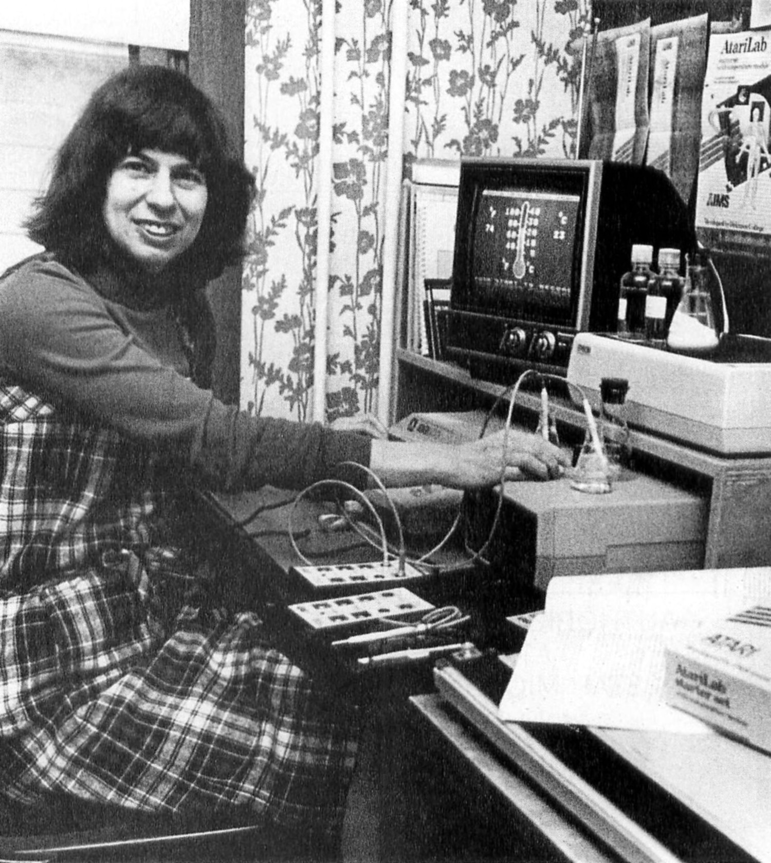
As part of the project she went to one of the Technical Education Research Centers (TERC) in Cambridge, MA — still around, but the acronym later became their name — where she saw work done by physicist and then-TERC science officer Robert Tinker using off-the-shelf sensors with the then-new Apple II to facilitate a computer-operated laboratory. Tinker's work with UC Berkeley educational psychologist Marcia Linn enabled students to run tests and experiments and share their results electronically, but what really excited Laws was that the computer did all the drudge work, plotting the output of the Apple's temperature probe thermistor in real time. "It blew me away," she said in 2015 in an excellent ANTIC Podcast interview (well worth a listen), "because when I had been teaching introductory physics labs, the students would spend all afternoon getting a cooling curve. And I immediately recognized that, hey, they could do things like, what if you dip it into oil instead of water, how is that going to change the cooling curve? Or what if you put insulation around the temperature sensor, how would that change the cooling curve? ... Think of all the experiments you could do in the same amount of time." Her concept of computer-aided experimentation directly translated to AtariLab's eventual box copy:


The product's retail price in class quantities was non-trivial for schools, so in addition to educational discounts Atari seeded the technology in early 1984 with a number of "test deployments" to build interest. (This was especially notable at the time as Atari was in the process of dismantling their educational direct sales network, which InfoWorld called "a shame.") Most schools used it for seventh and eighth grade. Some of these deployments yielded novel applications the team never considered, such as one Harlem school using the temperature probe to demonstrate heat from friction by rubbing it.


But Steigleman didn't stop there. The fire button inputs ("paddle trigger") were also used as digital inputs and read the same way, and the up and down joystick lines were brought out as two more. These were marked "CONTROL" because they were specifically intended to be outputs with POKEY so configured, which you could also do with the "PTRIG" paddle trigger lines. Finally, the +5V was brought out as power at the bottom along with a LED. Dickinson retained copyright on the board even during the time Atari sold them.


AtariLab became a hit with educators and the press, even if it wasn't a major commercial one, and it was a small bright spot for Atari during a very chaotic time. There were plans to bring it to the Commodore 64 and Apple II systems analogously to Atari's successful Atarisoft releases for other home computers, and Atari even announced it would be made compatible with the Atari 7800 ProSystem's doomed keyboard option. Other sensors were also discussed, including a "Crimelab" module for (presumably age-appropriate) forensic experiments, biofeedback modules or other galvanic skin response sensors, a pressure sensor, a timer module and even a ultrasonic motion sensor that got as far as the prototyping stage. But by June 1984 Warner was slashing staff — though Leslie Wolf remarked to the ANTIC podcast that confusion at payroll ensured she could keep a small production team shipping orders even after her precipitous departure — and everything was shut down upon the sale of Atari to Tramiel for $240 million on July 2, 1984.
While AtariLab was now officially dead on the Atari, Laws' group had already been working on the C64 and Apple II versions — the second entry in the AtariLab family tree — and when the rights reverted to Dickinson the college was able to find a new partner in Hayden Software. Hayden Software was the software-publishing arm of MacMillan's Hayden Books imprint (alongside sister brands like Howard W. Sams), most well-known then for the Sargon chess series, and released the starter kit as the Hayden Temperature Lab. Both products have a copyright date of 1985.
The Apple II version was actually fully developed but manufactured in very small numbers, and near as I can tell only the temperature module was produced. Laws' recollection in the ANTIC podcast is the the Apple version never shipped but it would seem odd to have full retail packaging for items that never got commercial sale, although later availability through liquidation can't be excluded, of course. These next few pictures are from various historical eBay auctions, though the aggregator I got them from does not attribute them, so hopefully the original sellers don't mind.


The Commodore 64 version of the Hayden Temperature Lab, however, came out before the Apple version, and although it is by no means common it is rather better known.


There was also a light lab release (picture here) that contained all of the Atari version's trinkets and instructional aids, even the glow stick.
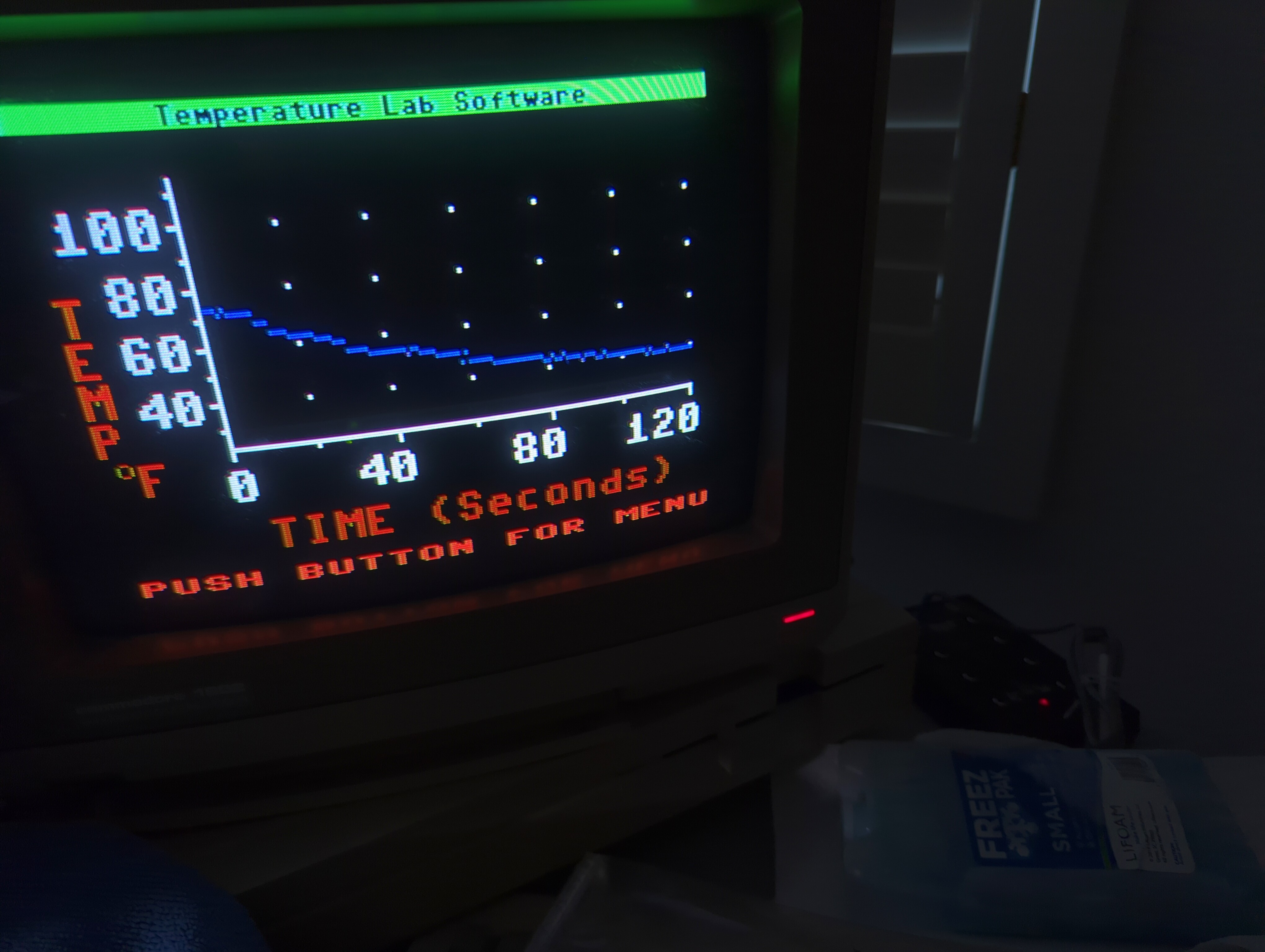
The fact the Hayden interface box is an AtariLab unit means that if you have an AtariLab box, and those appear regularly on eBay, then you can just use it with a Commodore if you can find the Hayden software. Fortunately (thank you, Steve!), we have a copy here at Floodgap HQ. So after all that preamble, let's sit down with this first "spawn of AtariLab" and play with it as a student would.


Let's first talk about how thermistors work. Thermistors are inherently non-linear devices; their resistance is more or less an exponential function. A very nice paper that goes into great detail is An investigation of the stability of thermistors by Wood SD et al., but to a first approximation the relation between resistance and temperature is expressed for an ideal thermistor by this function (MathML used on this page; test your browser or make sure you are using at least Firefox 4, TenFourFox, Safari 5.1, or Chrome 109 or the equivalent):
i.e., the thermistor generates resistance R for temperature T according to this formula, given R0 as the measured resistance for known temperature T0 and β as a constant (hang tight). Solving for T, then,
Let's stipulate for convenience that we will use "paddle units" of resistance (a measurement more or less linearly related to ohms) and degrees Kelvin, with 273.15 degrees Kelvin as our T0. If we have β and R0, then we can compute temperature given R. And there are default values, if we select Calibrate and Sensor:

Unlike Atari BASIC, which has a dedicated function for this purpose, paddles cannot be reliably read from Commodore 64 BASIC even with PEEK due to interference from the Timer A IRQ's keyscan. (The 128's BASIC 7.0 does support it.) Hayden thoughtfully included sample programs on disk to read and convert these values but I'm all about the wheel, as in the reinvention thereof. Here's a simple assembly language routine that will get the values for both paddle axes on both control ports and their fire buttons, copying them into the little section of memory between the default screen matrix and sprite pointers.
        * = $033c

; after bill hindorff's routine, c64 prog ref guide, p346
; I tweaked this to make return values more contiguous

porta   = $dc00
ciddra  = $dc02
sidx    = $d419
sidy    = $d41a

paddlex = 2024
paddley = paddlex+2
buttonb = paddley+2
buttona = buttonb+1

buffer  = 2

        ldx #1
        ; kill IRQs to prevent keyscan from messing with us
paddle0 sei
        lda ciddra
        sta buffer
        ; select port a
        lda #$c0
        sta ciddra
        lda #$80
paddle1 sta porta
        ; wait at least 512 cycles (no IRQs, remember, so no jiffy clock)
        ldy #$80
paddle2 nop
        dey
        bpl paddle2
        ; read pots
        lda sidx
        sta paddlex,x
        lda sidy
        sta paddley,x
        ; read buttons
        lda porta
        ora #$80
        sta buttona
        ; go back for next set
        lda #$40
        dex
        bpl paddle1
        ; finally get other buttons and restore IRQs
        lda buffer
        sta ciddra
        lda porta+1
        sta buttonb
        cli
        rts
Don't worry about assembling it: here's a BASIC program that you can just type in and run. Note that this routine is entirely reliant on cycle counts, so it may need to be modified for 2MHz mode on the 128 or if you're using a CPU accelerator.
10 sa=828:ck=.:poke198,.
20 ready:ify<>-1thenpokesa,y:sa=sa+1:ck=ck+y:goto20
30 ifck<>7816thenprint"error in data statements":end
40 sys828:printpeek(2024),peek(2026),peek(2028):printpeek(2025),peek(2027),
50 printpeek(2029):poke162,.:wait162,64:geta$:ifa$<>chr$(133)thenprint:goto40
5000 data 162,1,120,173,2,220,133,2,169,192,141,2,220,169,128,141,0,220,160
5010 data 128,234,136,16,252,173,25,212,157,232,7,173,26,212,157,234,7,173,0
5020 data 220,9,128,141,237,7,169,64,202,16,222,165,2,141,2,220,173,1,220,141
5030 data 236,7,88,96,-1
This displays the values of the paddle axes for port 1 and the fire button, followed by the paddle axes for port 2 and its fire button, waits for about one second, and does it again, over and over, until you press F1 or RUN/STOP.

% perl -e 'print (((273.15*4194)/(273.15*(log(103)-log(180))+4194))-273.15)'
10.3055026789538
in degrees Celsius, roughly the 11°C reported by the Temperature Lab. As we are taking a natural logarithm here, that means a paddle value of zero (i.e., no measurable resistance) would turn into a loge of 0, which is undefined. In practice getting such a reading would be almost certainly a malfunction.
It turns out that thermistors age too; the article we referenced above was in fact all about that very phenomenon, recommending that thermistors be pre-aged for specific applications to avoid drift ("It is clear from the data that thermistors to be used in accurate work where drift cannot be tolerated must be aged by either the user or the manufacturer"). Almost parenthetically, however, it also mentions that thermistors are sensitive to oxidation and while these probes are ostensibly sealed, things do open up over time. Plus, it's a certainty they were never high-end sensors to begin with due to AtariLab's cost pressures, along with a notorious scandal in Atari at the time where execs were getting kickbacks steering contracts to shady suppliers known to provide substandard components. (Laws herself comments on this in the ANTIC podcast we referenced, and it has an important part in the next descendant of AtariLab, so keep that story in the back of your head.)
Either way, we're dealing with sensors that were crap then, crappier now, and additionally (as of this writing) around 40 years old. We definitely need to recalibrate! I don't have the resistor plug nor know the value to make one, so we'll have to do this purely with the sensor.
Since the Temperature Lab wants a paddle units measurement at 0 degrees Celsius (273.15 degrees Kelvin), we'll go get a cold pack out of the freezer and jam the probe under that.

% perl -e 'print ((log(255)-log(103))/((1/273.15)-(1/(273.15+26.9))))'
2762.02064175617
So we should be able to plug the new beta of 2762 and P(0) of cough 255 into the Temperature Lab and get something in the ballpark now, right? Wrong:

That means — without cheating, that is — you can no longer get an accurate reading from an original thermistor probe and the standard AtariLab or Hayden software. How badly off? If we run those constants at the max the program will allow and let the probe adjust back to room temperature, we'll get this.


Is this the best we can do? Of course not! I did mention cheating, didn't I?
Notably, when changing the settings, the program will report "WAIT A MOMENT" and then "SAVING..." and write something to disk. If we look at the disk directory, there are files suspiciously named DEFLTCALTABLE (default calibration table), LEFT CALTABLE [sic], which must be the same for the left analogue input, and RIGHTCALTABLE. Strings in the file ATMC64, which is the Hayden lab main program, include @0:LEFT CALTABLE,P,W@0:RIGHTCALTABLE,P,W. These are save-with-replace filenames that explicitly write program files to disk, and no others so named appear in the file, meaning those are definitely the ones the software is overwriting. These tables look like this in a hex editor:
 00000000:  20 31 20 0d 20 34 31 39  34 20 0d 20 31 38 30 20   1 . 4194 . 180
 00000010:  0d 20 31 35 35 20 0d 20  32 35 35 20 0d 20 32 35  . 155 . 255 . 25
 00000020:  35 20 0d 20 32 35 35 20  0d 20 32 35 35 20 0d 20  5 . 255 . 255 .
 00000030:  32 35 35 20 0d 20 32 35  35 20 0d 20 32 35 35 20  255 . 255 . 255
 00000040:  0d 20 32 35 35 20 0d 20  32 35 35 20 0d 20 32 35  . 255 . 255 . 25
 00000050:  35 20 0d 20 32 35 35 20  0d 20 32 35 35 20 0d 20  5 . 255 . 255 .
 00000060:  32 35 35 20 0d 20 32 35  35 20 0d 20 32 35 35 20  255 . 255 . 255
 00000070:  0d 20 32 35 35 20 0d 20  32 35 35 20 0d 20 32 35  . 255 . 255 . 25
 00000080:  35 20 0d 20 32 35 35 20  0d 20 32 35 30 20 0d 20  5 . 255 . 250 .
Yup, they're just PETSCII. This is the default calibration of β=4194 and P(0)=180 (I don't know where the 1 or 155 come from). 256 values follow, all saturated to the 0-255 range. I made a few sample files with different values and got graphs like this, showing the curves are obviously logarithmic but relatively close in value:

But.
When loading the new table, obviously the table must have the beta and P(0) values in it, and to my nerdilicious delight it turns out the program will accept and manipulate them if they're already present, even if they're out of range. That means you can set the values in the file to β-1 and the new P(0) with a disk editor (right padded with spaces to four characters if necessary), then start up the Lab, go to calibrate the sensor and manually increase β up one to the desired value. The program will accept it as a valid changed value and faithfully re-calculate everything properly for you. Behold!


(A few notes as a postscript. Since we defined P(0) as 255, this calibration setup by definition can never measure below freezing, and it is likely there are similar constraints on the thermistor's other rated extreme. On the other hand, the AtariLab manual says it's rated for -5°C and up anyway, so we're not losing a lot. I did copy off the recomputed correct table and compared it with my calculated coefficients and found out I was as way off as the thermistor. Oh well.)
I don't have the Light Lab software and the Temperature Lab does nothing further with the CdS photosensor other than acknowledge its presence. Otherwise, Hayden never developed the product line beyond what was already available, and their rarity strongly suggests not many more of them were made or sold. But Priscilla Laws wasn't sitting around — so we're gonna connect the light lab probes to that.
In 1986, Laws and colleagues Robert Boyle and John Luetzelshwab collabourated on a proposal for FIPSE, the Fund for Improvement of Post-Secondary Education administered by the U.S. Department of Education. Laws was doubling down on the "workshop" approach to physics teaching and wanted to develop a calculus-based introductory physics course organized around hands-on experimentation and computer-based tools instead of traditional instruction. ("Students don't learn from lectures very well," she said on the ANTIC podcast. Three degrees later, I heartily concur.) By the fall the team had secured a three-year grant of $193,000 (in 2023 about $540,000) and a mandate to partner with Ronald Thornton at the Tufts University Center for the Teaching of Science and Mathematics, merging some of his group's curricular material into Laws' Workshop Physics units.
This work showed that better data collection tools and analysis were needed. Indeed, even on a shoestring budget no one was going to be putting undergrads on Atari XEs anymore, nor had more capable sensors and probes been developed for the older platform, and even the early PCs and Macintoshes of the era needed all of their processing power to handle greater and greater demands for analysis and display. As the FIPSE grants wound down, work started on a brand new interface to confront that very problem. Fortunately, Laws knew a guy who could do it.
Ron Budworth went through several engineering jobs at Atari which was where he first met Laws. In his role managing acquisitions, Laws explained on the ANTIC podcast, he stumbled across the Atari kickbacks-for-junk scheme and later was pushed in front of an oncoming train in Taiwan from which he only narrowly escaped. Deeply shaken by the incident and convinced the discovery would continue to endanger him, he quit the company. Laws subsequently approached him to handle the new system's hardware design, along with her, Thornton from Tufts and Tinker from TERC working on the specifications, which Budworth started developing in 1988 from their requirements as an independent contractor under the d/b/a "Transpacific Computer Company."
When it became clear the device would have potential commercial appeal, Tinker and TERC asserted ownership of the design until Laws' attorney objected, pointing out that Budworth had done the technical development substantially on his own with minimal direction (Laws says a recent federal court case was cited, though cursorily I was not able to find a matching opinion). The design was licensed to Laws' friends Dave and Christine Vernier, who had founded Oregon-based Vernier Software and Technology in 1981 (now Vernier Science Education) to sell Dave's educational software and hardware products; Laws rolled the $10/unit royalty into the grant funding for the courses using them. Production and sales started in 1990 of what was majestically dubbed the "Universal Lab Interface."


The DB-25 serial port connects to most computers with a standard modem cable (null modem not necessary); I use a standard DB-25 male to DE-9 female with my Linux RS-232 USB dongle. The AC adapter is a 9V 1A supply with a regular 5.5/2.5mm barrel jack, but unusually center-negative.
Officially the ULIs were sold and supported for the PC and Mac, though there's much more to them than that. In fact, they could be connected to and operated by any computer with a serial port — including Ataris and Commodores.

The CPU is an Intel 8032, the large DIP on the left side of the board marked P80C321, running at 12MHz from the crystal above it. This might seem surprisingly fast for this application except that the 8032 is a ROM-less Intel 8052, part of the MCS-51 family, and most instructions take about twelve clock cycles. Although this unit is marked as an early 1B, it appears to have been secondarily upgraded with later ROMs dated 1999. The board design is simple with relatively few components. ULI's documentation specify an SAB8032A-P but that designation was actually a second-source supplier (Philips).
The 8032 provides four 8-bit ports and three 16-bit timers. Being based on the 8052, it has 256 bytes of internal RAM (called IRAM) instead of the original 8051's 128 bytes, 128 bytes of which is directly accessible and used as registers, and the other portion indirectly so. In the 8051 architecture direct accesses to IRAM locations 0x80 through 0xFF reference special function registers like the accumulator, timers and I/O ports, but indirect access through the stack pointer or the first two registers will access the other 128 bytes when present.
The 8051 was designed as a Harvard architecture machine with its instruction set assuming separate and immutable program memory (though in practice some Von Neumann features are present with the external bus). As this is an 8032, all ROMs are external. An additional 8K of RAM is present in the ULI, here provided by a Mosel-Vitelic V62C51864L-70P 8Kx8 static RAM at U6, which is used for storage and buffers. Digital outputs come off the Motorola MC74HCT373AN at U2, an octal transparent latch with "totem pole" tristate outputs, used to allow the output to go almost all the way to "zero" volts. The SP720AP at U12 provides overvoltage protection while the Motorola MC74HC14AN at U8 provides Schmitt triggers on the digital inputs and the TI TLC2543IN next to C18 handles 12-bit A/D conversion on up to 11 analogue signals, though the ULIII exposes only ten analogue inputs to the user.


Connecting the AtariLab dongle to ULI port 1, let's plug in the thermistor first and turn on the unit. The red STAT light comes on to indicate it's waiting to set the serial rate. Rates from 300 baud (see, your Commodore 64 really can connect) to 38.4kbps are supported. On my Raptor Talos II workstation running Fedora Linux, we'll fire up picocom. You'll need local echo, so a command line like picocom -c -b 38400 /dev/ttyUSB0 or the equivalent options set in minicom should serve. Press the space bar and ...
ULI2 Rev. 1.40
H4/3>
... the ULI answers with its command prompt. The red status light extinguishes after the rate is set, which is normal; the green LED on the other side remains on. The H4/3 prompt says that the ULI is configured for hexadecimal output, that the accumulator is set to four bytes wide (i.e., it can count up to 232-1), that the buffer is in normal (the slash means ring buffer) operation, and that ports 1 and 2 are active (1+2=3).
H4/3>t000f42

H4/3>d

2C01
D4/3>
These commands tell the ULI to capture every 0xf42 ticks, which are 256 microseconds, so every 0.999936 seconds, and puts it into decimal mode for output. The response 2C01 says that the output values (here from DIN ports 1 and 2 simultaneously, even though we're only using port 1) will be separated by ASCII value 0x2c (i.e., a comma), with one record per line. You can pass different options with a command like d0901 which emits tabs between the values, one record per line. Notice that the prompt changed to a "D" to indicate decimal mode but hex mode would be very handy for a program trying to parse the ULI's output and that's probably why it's the default. You can also send data as raw bytes ("b" for binary mode).
At this point we're ready to stream data. The ULI deals in the concept of modes, which you can think of as saying which driver you'd like to use for the data an arbitrary probe will provide, and supports 15 such modes. Some of these modes are very complex and can even be gated on external digital signals to start and stop capture. For this application we will use mode 8; this mode records the voltage on the enabled ports at every specified capture interval. In fact, mode 8 actually works for many analogue sensors, even for ones you might obviously not think so. (On an original ULI with the probe connected to the proper resistance inputs, mode 3 would be more appropriate. Mode 3 returns an error on the new ULI.)
D4/3>m8

Data:
932,53
3927,50
3927,50
3927,50
3926,52
3927,50
3926,52
3927,50
3926,52
3924,53
3900,53
3930,52
We have both ports on, but nothing is connected to DIN port 2, so it just floats; the voltage on DIN 1 is the first number. This is reported in counts. An important difference between the O.G. ULI and the ULIII is that the new ULI has higher resolution: the O.G. ULI ranges from 0 to 1023 with each step being 0.005 volts, but the ULIII has four times the granularity, running 0 to 4095 in steps of 0.00125 volts. This is a new ULI, so with a median count of 3927 we get 4.90875 volts. The room is 81°F.
To prove it's live, I grabbed the probe and cupped it in my palm, and since the resistance must go down the voltage obligingly goes up. Because of the way we've wired this the difference is smaller than it should be, but the ULI is sensitive enough to detect it.
3935,50
3941,51
3944,53
3946,52
3949,51
3949,51
3952,53
3953,51
3952,53
3954,53
3954,53
3956,53
3954,52
3956,53
3955,51
3956,52
3958,52
3957,51
3956,53
You can halt the stream with Ctrl-C.
We don't know the provided current since the documentation doesn't say and my ammeter didn't get much of a value, but since we're being sloppy anyway we can abuse Kirchhoff's voltage law to compute a rough resistance in crapola units by dividing the voltage drop by the total voltage. The actual voltage on the port is 4096 times 0.00125 volts, making our rough figure ((5.12-4.90875)/5.12), or 0.04126. Let's go on hackilaciously and try to get R0 with a fresh cold pack to compute β. After a couple minutes we have stable values:
3578,52
3578,52
3578,52
3578,52
3579,50
3579,50
3579,50
3578,52
3578,52
3578,52
3579,50
3578,53
3578,52
3580,53
3579,51
3579,51
3578,52
3578,52
3578,52
The infrared thermometer on the cold pack read 30°F. For convenience, we'll calculate directly off the counts reported since they are proportional to voltage. With the cold pack we compute ((4096-3578)/4096), or 0.12646, as our R0.
Because β is an intrinsic property of the thermistor, we should get something similar to the AtariLab if we've done this at all correctly. Solving for β with our two temperatures being 269.55°K and 300.37°K:
% perl -e 'print ((log(0.12646)-log(0.04126))/((1/269.55)-(1/300.37)))'
2942.34706412162
And, well, it's within six or seven percent. That's not bad for screwing around! It's surprising the values are as close as they are considering differences in instrument precision, the limitations of the connection, how we fudged the AtariLab β a little before and how generally incompetent your humble narrator is.

D4/3>m8

Data:
3996,1217
3993,1474
3993,1543
3992,1563
3992,1569
And here it is with my thumb on it:
D4/3>m8

Data:
3586,1121
3354,1306
3357,1355
3392,1470
3393,1497
3415,1551
3378,1477
Can we convert this to a standard value like lux? Of course! Like the thermistor, photoresistors (light dependent resistors, etc.) have the same exponential relationship between light and resistance and have an analogous intrinsic constant per individual component. I don't have a lux meter handy here, but you would use the same computations and formulae, substituting the lux readings from your lightmeter in place of the temperature readings.
Let's try a couple ULI-specific sensors now. Of the wide variety of DIN and RJ-11 capable Vernier sensors that would be compatible with the ULI, I found these two cheap on eBay (that's what your tips to Old VCR on Ko-Fi pay for, among other things):

Notably, the heart-rate monitor is essentially a light and a corresponding photoresistor in a fingertip or earlobe sensor (the black box is an adjustable amplifier). This is not sufficient for pulse oximetry, which relies on detection and absorption of specific wavelengths of light, but it's more than adequate for a basic photoplethysmogram. That said, we'll need to capture much faster than one per second if we're going to get a reasonable pulse waveform. There is at least one documented case of a human heart rate at 600 beats per minute (!), but for the vast majority of people we'll be looking at a pulse rate no more than 150bpm, or a pulse every 0.4 seconds. That just gets us peaks, though, not a full waveform, so we'll say we'd like 10 samples per pulse. 40,000 microseconds divided by 256 is 156.25, so we'll select a time interval of 0x9c. While we're at it, we'll turn off the other port for data (we have it connected to DIN 2).
D4/3>t00009c

D4/3>s2

D4/2>
Since it's just another analogue sensor, it also runs in mode 8 (m8). It may take several seconds for the waveform to be detectable, so I'd start by attaching it to your earlobe for the best chance of a good signal but your fingertip or hand web space should also work. You should get a sinusoidal waveform from the numbers if it's sensing right. If not, try adjusting the pot accessible through the little hole in the amplifier box with a 5/64" flathead; I ramped it up all the way (turn clockwise).


Incidentally, if the 256 microsecond time base starts becoming inconvenient, you can set it to any value between 1 and 256 (0 is treated as 256) with the "e" command, though the parameter must be provided in hexadecimal. The value is in microseconds, so e64 sets a timebase of 100 microseconds or efa sets it to 250, and then the value you stored with the "t" command is measured that way.
In this example we were capturing much faster than we did before. You may wonder what happens to data that arrives faster than the ULI can transmit it, particularly on a system with a slow serial link like a Commodore 64 via the user port (generally limited to 2400 baud without UP9600), but it turns out that's no problem: by default every value acquired by the ULI is buffered in the 8K external RAM. You can even have the ULI signal you (using the "j" command) if the buffer overflows. You can also command the ULI to capture very quickly to RAM first and then transmit, either as a one-shot or repeatedly (the "!" and "*" commands); the O.G. ULI can capture 13,600 samples per second and the ULIII 11,000 samples per second, owing to the overhead of the 12-bit A/D conversion.
Vernier also made an EKG monitor with a DIN connector that would work with the ULI, though it's only a two-lead that would generate what we'd call a rhythm strip instead of a full 12-lead EKG (also a full 12-lead may involve shedding more clothing than would be acceptable in a non-medical learning environment). Naturally they take pains to remind you that none of this should be used for clinical or diagnostic purposes.


The basic motion detector functionality runs in mode 2. Selecting the time interval is a bit of a balancing act because you need to allow sufficient time for the echo to return, but not be so slow that you would miss changes in the environment. The manual suggests that 0.01 seconds between readings (t000027) gives you only a maximum range of 1.72 metres, but at 0.04 seconds (t00009c) you get a range of 6.88m. Since I'm just sitting at my desk typing this, we'll use half a second (0007a1).
Now you see me:
D4/3>t0007a1

D4/3>m2

Data:
4138,0
4196,0
4195,0
4203,0
4211,0
4184,0
4208,0
4076,0
Now you don't:
D4/3>m2

Data:
12665,0
13217,0
12891,0
13176,0
13417,0
14362,0
13930,0
12852,0
14153,0
12245,0
Here we are receiving input from RJ-11 port 1 and 2, not DIN 1 and 2. Each of these records report out the round-trip time in discrete microseconds. When I was seated, the roundtrip time was about 4200us, so turning the propagation speed into 343 millimetres per millisecond for convenience, we get (0.5)(4200)(0.343) = 720.3mm or 28.36 inches. Getting out a yardstick and eyeballing it, I reckon 27ish inches from the sensor to my face where it was pointed, but the distance sensor is probably more accurate.
Standing up, the distance sensor's next closest item in view (at the angle the pivot hinge is set to) is the doorframe. The distance and the variable reflectivity make that roundtrip time noisy, so we'll take a formal average of 13291us. That yields (0.5)(13291)(0.343) = 2279.4065mm or 89.74 inches. Manually I get about three yardsticks' distance from there to the wall; again, it's probably more right than my quick measurement.
It would be nice to have a mode where you could gate some operation on the distance measurement changing by an arbitrary threshold, but the ULI doesn't support that. However, mode 9 does allow combining distance measurements with an analogue sensor. This was used in experiments like this one:

The ULIII was the last such commercial device linked to Priscilla Laws, and the last direct descendant of the AtariLab. Vernier made and sold other interface boxes that could use many of the same probes, however, one of the most common being the Serial Box Interface. This was packed in apparently with several systems but my personal favourite is the 1997 eProbe, which was released by Knowledge Revolution for Newton OS-based devices (specifically the laptopesque eMate):


There is no obvious CPU anywhere, and only one interesting IC with a Vernier sticker on it. If we peel off the sticker, we see this:

Over its lifetime the ULI series sold over 40,000 units, which strikes me as surprisingly good for such a niche product. However, no attempt was made to update them in the post-serial-port world (though some do work with USB-serial dongles as they do here with my Linux workstation) and the Mac logging software in particular that supported the serial box systems was never made OS X-native. Instead, continuing its partnership with Texas Instruments, Vernier rebadged the Texas Instruments Calculator-Based Laboratory 2 in 2000 as the LabPro. A device similarly programmable to the ULI, but smaller, faster and compatible with USB or serial, the ULI and other serial-only interfaces were quietly discontinued. Today Vernier remains one of the leading vendors of educational scientific technology.
As for Dr Laws, as technology improved she went on to designing more sophisticated software at the university level in her continued efforts to make instruction more hands-on; as of this writing, she remains listed as a research professor at Dickinson. And, well, her approach still seems to be sound: writing this article I ended up doing far more benchwork in basic physics than I think I ever did as an undergraduate. So score one for AtariLab.
No comments:
Post a Comment
Comments are subject to moderation. Be nice.